


News
Inverter use for PID control pressure water supply control-AVI
2015-08-01
Inverter use for PID control pressure water supply control.
Sample :(User requirement)
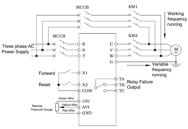
Keypad given setting pressure. pressure gauge is as feedback signal .external pushbutton start . require pressure is 0.5MPa. If the pressure is higher than 0.5MPa.the inverter decrease the speed. When the frequency reach to 30.00Hz. and the pressure is still higher than 0.5MPa.the inverter stop automatically . the inverter will start automatically when the frequency reduce to 0.4MPa.The measure range of pressure gauge is 0.0~1.0MPa.If the inverter failure can be working frequency and running by manual .the parameters can be set as follows :
F0.01—Running channel source selection. F0.01=1—External terminal control
F0.03—Main frequency channel source selection .:F0.03=5—PID Control;
F0.06—Lower frequency limit : F0.06=30.00Hz.
F5.00—Input terminal X1 function selection ; F5.00=1-Forward Running.
F5.01—Input terminal X2 function selection:F5.01=7—External Reset input
F9.00—PID given source selection:F9.00=0—Keypad Setting ;
F9.01—PID given value:F9.01=50.0%—Keypad setting 0.5MPa as pressure .
F9.02—PID feedback source selection : F9.02=0 – External voltage feedback.
F9.03—PID output characteristics selection . F9.03=0- PID output is positive .
F9.04—Proportional gain Kp. No need to change .
F9.05—Integral Time Ti. No need to change .
F9.06—Differential Time Td. No need to change .
F9.07—Sampling Cycle T: No need to change .
F9.08—Bias Limit .No need to change .
F9.10—feedback lost detecting time ::60.0s;
F9.11— feedback gain : to correct the error of the feedback value and pressure gauge .No need to change .
F9.12—Awakening threshold :40.0%;
F9.13—Awakening Threshold detection time . no need to change .
F9.14—Sleep Threshold:50.0%;
F9.15—Sleep threshold detection time. Set according to actual request .
When use the PID function ,In order to meet the control demands .Customers can modify the parameter according to the actual request .
How to set F9.01;Please see as follows:
F9.01=1/preesure measure *required setting voltage *100%.
The contactor KM1,KM2 are shifting from working frequency to variable frequency .Must be designed in interlocked manner ,It is forbidden to close the two contactors at the same time . Otherwise. the inverter will be permanent damaged .